The RT-1000 VDF system is designed specifically for ATC and VTS applications and complies with ICAO and DFS (Deutsche Flugsicherung) requirements.

The RT-1000 radio direction finder, which has become the benchmark in its class, is also known under the Rohde & Schwarz designation PA030. More than 150 systems are currently in use worldwide.

Special Features

• Doppler radio direction finder
• 8.33 kHz channel spacing in the VHF air band available
• Extremely high rotation frequency for fast signal processing
• Compact antenna system for simple installation
• Antenna location independent of controller workstation
• No infrastructure required for remote operation
• Maintenance-friendly modular construction
• RS-232 interface to permit system integration
• Frequency range: Aviation band: 118.000 to 136.975 MHz
• Frequency range: Marine band: 156.000 to 174.000 MHz
• Various scanning modes
• Secound simultaneous channel optionally available
• Special antenna mast with test and maintenance functionality

Technical Data

Frequency Range

ATC: 118 to 136.975 MHz
VTS:156 to 174 MHz

Operating channels

ATC (25kHz): 760
ATC (8,33kHz): 2278
VTS: Channel 01 to 88 including Duplex channels

Channel spacing

8.33 kHz / 25 kHz

Bearable modulation types

A3E, F3E, A3X (ELT-modulation)

Bearing accuracy

2° RMS
(±1° with bearing precision improvement option)

Bearing sensitivity

VHF Airband oder Marineband
≤ 5 µV/m / 2 µV/m typical at ±2° bearing fluctuation
VHF Airband or Marineband including 2nd bearing channel
≤ 5 µV/m / 3 µV/m typical

Polarisation

Vertical

Polarisation error

±1° (with field vector rotation up to 45°)

Cone of silence

approx. 35° referred to the vertical

Power supply

AC: 115 / 230 V ±15%; 47 to 63 Hz
DC: 24 V -10% / +20%; automatic switch-over to DC voltage in case of AC mains failure

Power consumption

Controller unit: max. 15 VA
Receiver unit: max. 10 VA (65 VA with heater)

Temperature ranges

Operating temperature:
Antenna: -40° to +80°C
Receiver unit: -40° to +60°C
Controller unit: -20° to +55°C

Storage temperature: -40° to +60°C

Interfaces

serial V.24 (RS232)
parallel

Response time

Display: ≤ 400 MS
RS-232 Output: ≤ 450 ms

Variant A)

Digital: 3 digits with 7-segment LED indicator
Resolution: 1°
Bearing reference: QDM, QDR, QUJ, QTE
Updating rate: approx. one indication/s

Variant B)

Dual compass dial: 2 concentrical circles of LED points
Resolution: 10°
Bearing reference: QDR

Updating rate:
Outer circle approx. one indication per secound
Inner circle 47 indications per secound

Audio

Built-in speaker
Headphone Output

Ground transmitter suppression

with external contact to ground

Lateral thrust due to wind

with constant wind speed
150 km/h approx. 135 N
180 km/h approx. 195 N
(data including lightning rod and mast)

Dimensions and Weight Controller

9"-desk-top model 3 UH, prepared for rack installation
Dimensions (H x W x D): 132.5 x 448 x 370 mm
Weight: 8.1kg

Dimensions and Weight Receiver unit

Non-metallic cabinet for wall mounting (IP 65)
Dimensions (H x W x D): 250 x 340 x 285 mm
Weight: 6.9kg

Dimensions and Weight Antenna

Dimensions (Diameter x H): 400 x 1120 mm
with lightning rod and mast: 400 x 3400 mm
Weight including antenna rods: 3.8kg

Methode of Bearing

Doppler-principle (3kHz rotational frequency)

Footnote 1)

....

Accessories

DF Commander

Full width df commander test 2

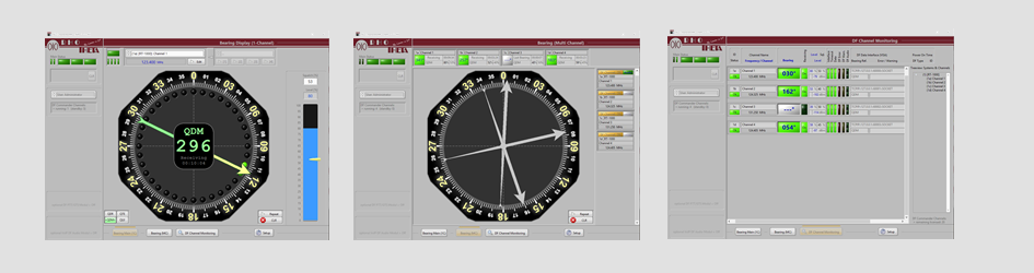
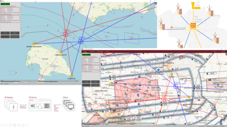
The main purpose of the “DF Commander" Software is to provide the remote control and monitoring of multiple DF-Channels and DF-Systems from a standard PC. This software allows the visualizing of the bearing data, such as bearing angle, signal level and frequency of an appropriate channel. The simple and convenient design of the “Bearing Page” and the possibility to adjust the orientation of the compass rose towards the tower window view makes the controller’s work very comfortable.

Furthermore the software provides the possibility to simultaneously monitor the status of all channels connected, which is also a helpful feature for the technical monitoring and maintaining of the DF-System.

DF Commander MK2 Software

Full width df commander mk2 titelbild

The DF Commander MK2 software enables remote control and monitoring of radio direction finding systems. Besides displaying the direction finding results on different electronic charts, the software is able to calculate cross bearings on different frequencies. Soundings, cross bearing results and status information of radio direction finding systems are made available via an integrated server. Radio direction finding systems can also be set and controlled via the same server. Thus the software is to be understood as a DF service.

Antenna Model

Full width antennenmodel zubeh%c3%b6r bild

The antenna model simulates the radio direction antenna. If the antenna model is connected to a signal generator, it delivers a signal like a DF antenna under perfect conditions. It simulates the signal angle 0 °; 90 °; 180 ° or 270 ° at its RF output;
The antenna model is a very useful device for the maintenance of the DF system.

Antenna mast with test and maintenance functions

Full width rt 1000 mast mit test funktion hp

The antenna mast is a girder mast which has been developed especially for the Doppler antenna system RTA 1300, which makes possible the turning and titling of the antenna for assembly and maintenance purposes. The mast will be delivered in disassembled condition. It has to be mounted and grounded after the assembly on a suitable base. The scope of delivery also includes a waterproof installation box, in which the receiver unit and remote data transmission can be located. All parts of the mast and the bolted connections are hot-dip galvanized or respectively made out of stainless steel.

Obstacle Light

Full width hindernisbefeuerung hp

The Obstacle Light is an optional safety accessory for the RT-1000 antenna mast. There exist two orderable variations: Single Obstacle Light and Double Obstacle Light. Both variations are intended for mounting on the top of the RT-1000 antenna mast.

Single Obstacle Light is a single-light-construction, which contains a light bulb in its housing and a corresponding mounting frame.

The Double Obstacle Light is a construction with two lights, which have an identical structure as the Single Obstacle Light. While the first lamp is in operation (operation lamp), the second lamp is in standby (standby lamp). In case of the failure of the operation lamp, the standby lamp will be automatically switched on. Furthermore the construction includes the IP 64 connection box and the corresponding mounting frame.

Antenna Mastflange

Full width mastflansch hp

The antenna mast flange allows the installation of the RT-1000 antenna on any construction. CAD drawings for integration are available on request.

Additional Bearing Channel

Full width receiver und controller hp

The bearing system can be equipped with an additional receiver module and an additional controller. In this way, two workstations can work on different frequencies simultaneously with the system.

DF-Emulator Software

Full width df emulator hp

The "DF Emulator" is a software that emulates a bearing system on a Windows PC by playing a pre-recorded log file. In the simplest case, the DF emulator uses the serial COM port of the PC to transfer the data via RS232 to another PC or system that displays the bearing data.
This software is designed for projects like bearing data integration in radar displays or other map- and control displays and is intended to facilitate the work of integrators.

SNMP Modul

Full width snmp modul ii

SNMP Module is an optional hardware that provides the remote error monitoring of RHOTHETA RT-1000 direction finder systems over the Simple Network Management Protocol.

Applications

Navigation

Thumb navigation bu hne 01 1140x350

Radar Identification

Thumb radar bu hne 114x350

Vessel Traffic Service (VTS)

Thumb vts bu hne 02 1140x350

Coast Surveillance

Thumb vts ku%cc%88stenu%cc%88berwachung 1140x350

References

DF Renewal Project South Africa

Thumb tellumat

skyguide - swiss air navigation services ltd

Thumb skyguide snipimage logo   foto